VALIDATION OF VIC-3D® BY FORWARD AND INVERSE BENCHMARK
EXPERIMENTS
Harold A. Sabbagh, Elias H. Sabbagh, and R. Kim Murphy
Victor Technologies, LLC
P.O. Box 7706, Bloomington, IN 47407-7706 USA
(Presented at 28th Annual Review of Progress in Quantitative
Nondestrucitive Evaluation
Bowdoin College, Brunswick, ME, July 29-August 3, 2001)
(a) Forward Problem: Cracks with Complex, Double-Peaked Shapes
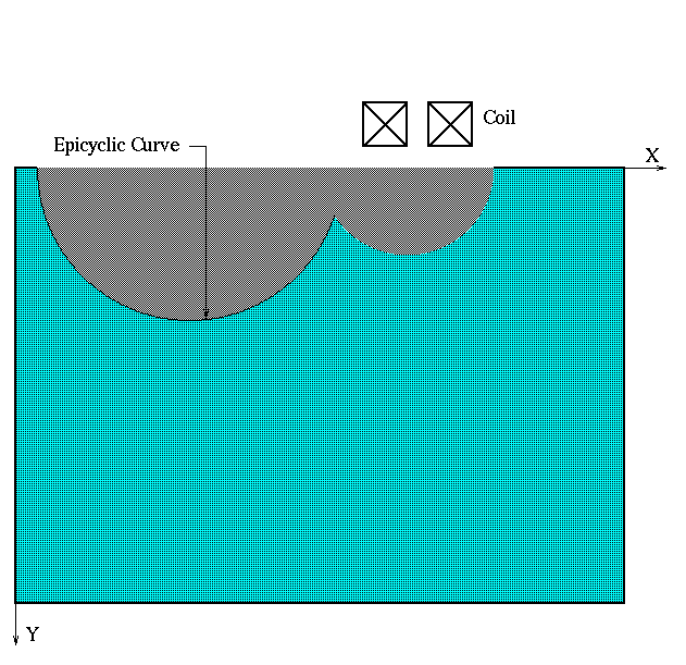
These cracks, such as that shown in Figure 1, are well suited to model damage
arising from multiple sites.
|
 |
| Figure 1:A double-peaked, epicyclic crack, that is suited to model multi-site damage. |
|
|
|
In [1], Harrison et al have developed a set of four benchmark
problems for verification of theoretical calculations of defect size and
shape in eddy-current NDE. The benchmark problems are based on careful
measurmements of the change in impedance associated with slots of
semi-elliptical and double-peaked (epicyclic) profiles. Later, we will
give examples of the inversion of such impedance data, but here we will
present results of applying VIC-3D® to the computation of the
forward problem for slot D2 of [1]. This slot is epicyclic, with two
peaks, the larger about 8.94 mm, and the smaller about 6 mm. The length
of the slot is 49.78 mm, and the width 0.37 mm.
The coil possesses an air core, and has an inner radius of 2.51 mm,
an effective outer radius of 7.38 mm, a height of 4.99 mm, and an
effective lift-off of 0.2 mm. It is wound with 4000 turns, and excited
at a number of frequencies. In our modeling effort, we considered only
excitation at 250 Hz. The effective value of the conductivity of the
workpiece is 2.24× 10⁷ S/m.
In modeling the profile of the flaw, we use the approach of [2],
wherein we represent the epicyclic profile of the crack in parametric
form as
| x=a(1)cos(t)+a(2)cos(2t)+........ |
| y=b(1)sin(t)+b(2)sin(2t)+........ |
where t is the independent parameter.
Bowler and Harfield [2] have determined that flaw D2 can be
approximated using fifth-order epicycles, with coefficients whose values
in mm are listed in Table 1
| a(1) = 22.093 |
b(1) = 7.400 |
| a(2) = -2.526 |
b(2) = -1.522 |
| a(3) = 3.354 |
b(3) = 2.616 |
| a(4) = -0.083 |
b(4) = -0.074 |
| a(5) = -0.570 |
b(5) = -0.536 |
Table 1: Coefficients for D2, according to [2].
In modeling the flaw with VIC-3D®, it is necessary to use enough
cells to capture the shape of the flaw's profile, so we used a mesh of
2× 64×16 cells in, respectively, width, length, and depth.
The probe is scanned over a length of 120 mm, in one mm steps, in
accordance with the measured data.
Our first task is to use the parametric equations and the expansion
coefficients to determine the volume-fractions that define the flaw for
VIC-3D®. This is easily done using a simple two-point Gaussian
quadrature routine. The volume-fraction data are then quickly read into
the .vic file, which VIC-3D® then executes to produce the results.
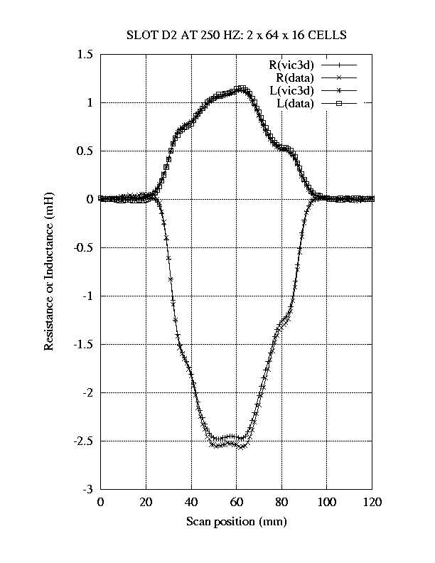
The results of the model calculations are compared to the
measurements in Figure 2.
Clearly, the agreement is excellent.
|
|
 |
| Figure 2:Comparison of forward-model results, calculated by VIC-3D®, with measured data for flaw D2 of [1] at 250 Hz. |
|
|
|
(b) Inverse Problem: Cracks with Complex, Double-Peaked Shapes.
In this section we apply VIC-3D® to the problem of reconstructing
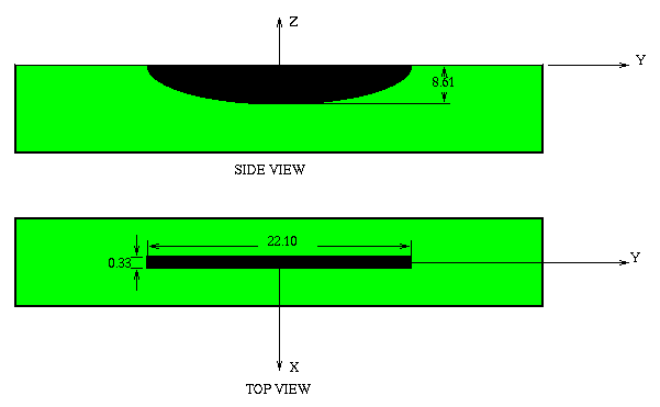
two flaws, D1 and D2, that are described in [1]. D1 is a semielliptical
slot, shown in Figure 3, and
D2 is the same flaw that was described in the previous section.
|
 |
| Figure 3:The semielliptical slot, called D1 in [1]. |
|
|
The objective is to take the measured data of [1], and invert it to
determine the shape of the scattering body, namely the semiaxes of the
flaw. For this exercise, we used data at 250 Hz, comprising the change
in resistance and self-inductance (in mH) measured at the five probe
positions -22.5 mm, -17.5 mm, -12.5 mm, -7.5 mm, -2.5 mm. These give us
10 data points with which to determine the two real unknowns (the
semiaxes). The coil is the same as before, except that the effective
lift-off is 0.3 mm, instead of 0.2 mm. The conductivity of the
workpiece is 2.25×10⁷ S/m.
As its contribution to the inversion process, VIC-3D® is used to
create an a priori table of possible changes of resistance and
inductance at the same five points, when the length semiaxis takes on
values of 9, 10, 11, 12, and 13 mm, and the depth semiaxis takes on
values of 6, 7, 8, 9, 10 mm. This gives us 25 values of resistance and
inductance at each position of the probe. In order to generate these
data, VIC-3D® is run twenty-five times, with the five scan positions
for each run. VIC-3D® includes a semielliptical flaw in its
library, so it was not necessary to compute volume-fractions for each
of the twenty-five combinations of flaw shape. Each of these
twenty-five runs used a grid of 2× 32× 16 cells (width,
length, depth).
The inversion process employs a nonlinear least-squares algorithm to
fit the solution vector to the data. During the inversion, the function
values are determined from the table, with the entire process being
completed in a few seconds.
The computed answer for D1 is 8.21 mm and 11.50 mm for the semiaxes,
whereas the actual values (as measured from cast rubber replicas) are
8.61 mm and 11.05 mm. This agreement, with an error less than 5%, is
considered quite good, given that there was an absolute uncertainty of
0.5 mm in locating the center of the flaw when taking the data.
Now, we go to the reconstruction of D2. By this we mean that we are
going to determine the expansion coefficients b(1) to b(5) in the
parametric representation of the depth variable, y, while assuming that
expansion coefficients, a(1) to a(5), that define x remain fixed.
Because these latter coefficients determine the length and center of the
flaw (in the x-direction, of course), we are agreeing that we know
these parameters of the flaw, and wish to reconstruct the profile in
depth.
Of the given (measured) data, which were determined at
one-millimeter increments from -60 mm to +60 mm, we chose eleven points,
comprising the change in resistance and self-inductance (in mH) from
-31 mm to +29 mm in six-millimeter increments. This results in a total
of twenty-two equations for the five unknowns.
As in the case of D1, we use VIC-3D® to generate an
interpolation table for the five unknowns, with each unknown taking on
two values in the table. This means that we must run VIC-3D® 25=32
times in order to generate the table. The thirty-two combinations are
generated by letting the b(i) take on the values shown in Table 2:
| b(1) = 7 , 8 |
| b(2) = -2 , -1 |
| b(3) = 2 , 3 |
| b(4) = -0.10 , -0.05 |
| b(5) = -1.0 , 0.0 |
Table 2: Values assigned to the b(i) in order to
generate the interpolation table.
We used the same nonlinear least-squares algorithm as in D1 to do
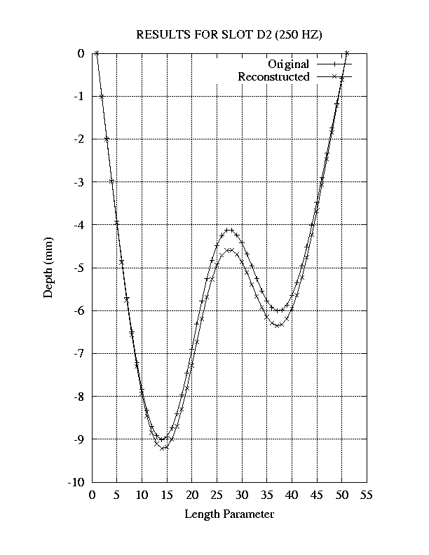
the inversion, and got the results shown in Figure 4
|
 |
| Figure 4:Reconstruction of epicyclic flaw D2 of [1]. |
|
|
The computed values of the b(i) are listed in Table 3:
|
Computed |
Original |
| b(1) |
7.818 |
7.400 |
| b(2) |
-1.454 |
-1.522 |
| b(3) |
2.580 |
2.616 |
| b(4) |
-0.050 |
-0.074 |
| b(5) |
-0.526 |
-0.536 |
Table 3: Results for inversion of D2 data.
References
[1] D. J. Harrison, L. D. Jones, and S. K. Burke, ``Benchmark
Problems for Defect Size and Shape Determination in Eddy-Current
Nondestructive Evaluation,'' J. Nondestructive Evaluation, Vol.
15, No. 1, March 1996, pp. 21-34.
[2] J. R. Bowler and N. Harfield, ``Thin-Skin Eddy-Current
Interaction with Semielliptical and Epicyclic Cracks,'' IEEE Trans.
Magnetics, Vol. 36, No. 1, January 2000, pp. 281-291.
|
|
|