ASSESSING THERMAL BARRIER COATINGS BY EDDY-CURRENT INVERSION
Harold A. Sabbagh, Elias H. Sabbagh, R. Kim Murphy
Victor Technologies, LLC
P.O. Box 7706, Bloomington, IN 47407-7706 USA
John Nyenhuis
Purdue University
West Lafayette, IN 47907-1285
(Presented at ASNT Fall Conference and Quality Testing Show--2000
Indianapolis, Indiana November 14-17, 2000)
Introduction
Advanced turbines, such as the GE Frame 7FA/9FA, are used in
applications ranging from aerospace to land-based power generators.
These turbines are fired at higher temperatures (1850° F-1950°
F), and utilize optimum cooling of hot section components. Because of
the higher operating temperature, the performance and durability of the
first stage blades has become one of the prime life-limiting factors.
Individual blades are nickel-based GTD 111 alloys, that are protected
by sacrificial metallic coatings to extend service life. The
first-stage blades are especially important, and it is desirable to
develop an in-situ NDE system to monitor, evaluate, and predict
remaining coating life. The coatings used on the turbine blades include
CoCrAlY and NiCoCrAlY, with a top aluminide coating (GT29+, GT33+,
respectively), and a NiCoCrAlY coating, called PWA 286 (EPRI(1), 2000).
Victor Technologies has been performing research into the
nondestructive characterization of in-service high-temperature metallic
(such as MCrAlY) thermal barrier coatings (TBC) applied by vacuum
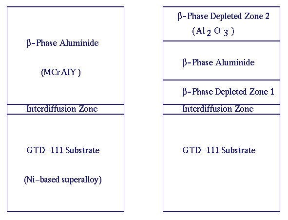
plasma spray on Ni-based superalloy turbine blades. Figure 1 illustrates an as-coated PWA286
coating on a GTD111 substrate and the same coating after aging.
|
|
 |
| Figure 1: An as-coated PWA286 coating on a GTD111 substrate (left) and the same coating after 2400 hours (right). |
|
|
|
All coatings form a thin protective adherent layer of Al2O3.
As the protective oxide spalls off during service, aluminum in the
coating diffuses out to re-form the protective oxide layer, and also
diffuses into the substrate and causes the interdiffusion zone to
increase in thickness. Thus, the coating degradation is represented by
the transformation of beta-phase NiAl into a gamma-matrix of solid Ni
solution. The gamma-matrix is represented in the figure as beta-phase
depleted zones. Therefore, the diffusion zone thickness increases from
the addition of the beta-phase depletion zone (Zone 1), that is located
just below the coating (EPRI(1), 2000).
The primary objective is to estimate the equivalent thickness of the
aluminum beta-phase content of the PWA286 coating. This information is
essential to maintaining the integrity of blades, because it allows
the timely repair or refurbishment of coatings to extend the
service-life of operating blades. Further, it is desirable to obtain
the interdiffusion layer thickness, since this information indicates
the level of blade exposure to service temperature. The overall
remaining coating thickness indicates the reduction of the coating
thickness caused by the oxidation-induced degradation of the top
beta-phase depleted layer (EPRI(1), 2000).
We have performed a number of model calculations of the TBC problem,
using our proprietary eddy-current NDE code, VIC-3D®, and have
determined important system features, such as operating frequency, coil
characteristics, electronic test equipment considerations, and means of
accelerating the computations. As a result, we have concluded that the
optimum frequency range for performing the inversions required of the
TBC problem is 10MHz to 200MHz. Successful inversions in this range
will allow us to achieve the desired resolution for these extremely
thin coatings.
Because there are no commercially available eddy-current instruments
that operate in this frequency range, we used the Hewlett-Packard HP
3577A Network Analyzer, that is designed to operate over the frequency
range of 5Hz to 200MHz. This instrument measures the reflection
coefficient of a one-port network (namely, the loaded coil), from which
the impedance data, that are the input to the inversion algorithm, are
determined.
There are several steps to be carried out during the testing. First
will be to characterize the probe in free-space, then to collect the
impedance data, and finally to invert these data using our
`8layer-algorithm.'
Determining Coil Parameters
The coil used is a Zetec Z0000595-1 ultra high frequency pancake coil,
that is designed to operate in the range of 10 to 100 MHz. Its
dimensions are 0.090 inch outer diameter, 0.025 inch inner diameter,
0.008 inch height, and is wound with 19 turns. For the purpose of this
demonstration, the coil was housed in a Plexiglas block, and the test
pieces were laid on the block, over the recessed coil.
VIC-3D® assumes that the probe coil is an ideal inductor that
carries a uniformly distributed current within a rectangular window.
This is the basic assumption in most theoretical models for
eddy-current NDE. In practice, any real coil exhibits self-capacitance
and resistance, as well as additional capacitance associated with
coaxial cables or other connections to the coil. Furthermore, the
assumption of a uniform current-distribution cannot be supported in a
real coil, because such coils use windings of wire with circular
cross-sections, and these windings are never uniformly distributed, as
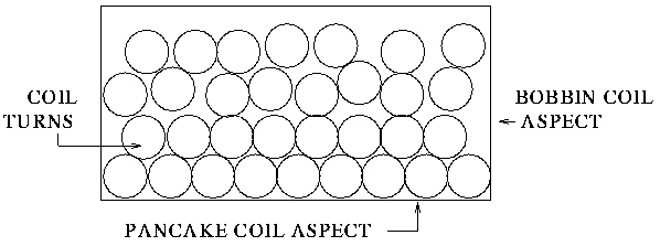
shown in Figure 2.
Furthermore, skin and proximity effects give rise to nonuniform current
distributions within the wires themselves. These deviations from ideal
behaviour must be taken into account if good agreement between theory
and experiment is to be obtained over a significant frequency range.
|
|
 |
| Figure 2: Showing a nonuniform distribution of turns within a typical real coil. |
|
|
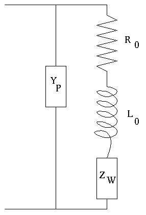
A real eddy-current probe can be modeled by the equivalent circuit
of Figure 3, in which L0
and R0 are the (low-frequency) inductance and
resistance of the probe, ZW is the impedance of the
workpiece (with or without the flaw), coupled back into the probe
circuit, and YP is the parallel admittance that
accounts for the remainder of the probe and its connecting cable. For
example, YP could be the self-capacitance of the
coil, as in Figure 4, which
would account for the resonant behavior of the probe. In any case, we
assume that Yp goes to zero as the frequency goes to
zero.
|
 |
| Figure 3: The equivalent circuit of a real eddy-current probe. We assume that YP goes to zero as the frequency goes to zero. |
|
|
 |
| Figure 4: The equivalent circuit of a real eddy-current probe, showing the presence of the self-capacitance of the probe, which accounts for the resonant behavior of the probe. |
|
|
VIC-3D® has a filter that removes the effects of YP,
thereby correcting the data obtained when using a real coil, and
transforming them into data that would be obtained by using the
equivalent ideal coil.
Data Collection
Using the HP network analyzer and the Zetec coil, we measured the
reflection coefficient, S11, from one to fifty
megahertz, in one-megahertz steps, for each of the fourteen test
samples (top and bottom of each sample). S11 is
recorded as a magnitude and phase (in degrees), as shown in the
following figures. Figure 5
shows S11 for the coil in air, i.e., away from the
test samples.
|
|
|